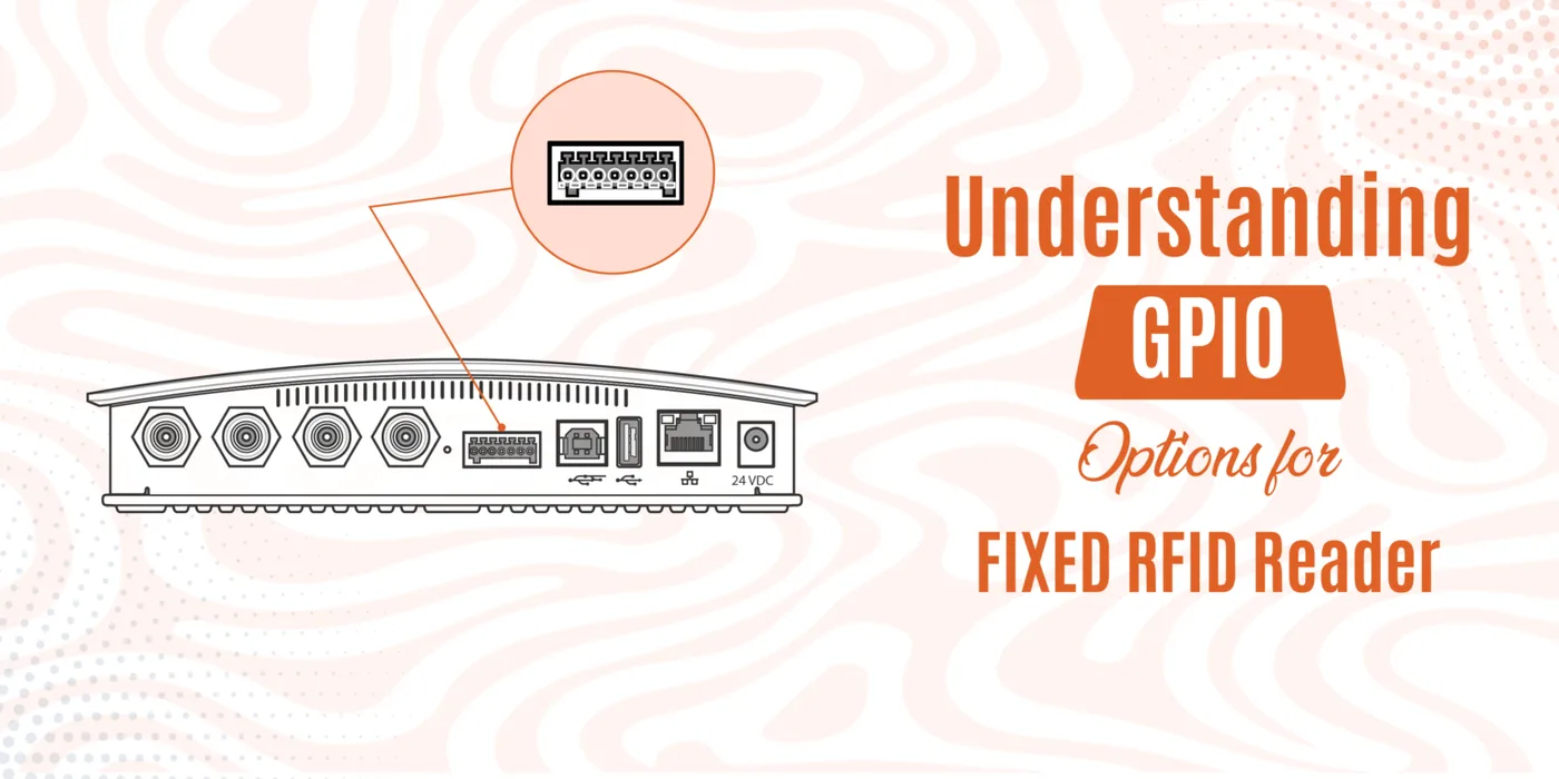
A fixed reader reports what it sees but changes nothing on its own. GPIO is the interface that lets it receive signals from switches and sensors and drive the devices that act on a read — and the setup order that keeps those signals honest.
01 / FIELD NOTE
Keep the decision tied to the operating context.
A fixed reader that only reports a read has delivered information and changed nothing. The tag appeared in the field, the software logged it, and whatever should happen next — a door releasing, a light switching colour, a conveyor diverting a carton — waits for another system or another person to notice. GPIO is the mechanism a fixed reader uses to reach into the physical process itself: pins that listen for signals from switches and sensors, and pins that send signals to the devices that do the work.
A GPIO pin is an electrical terminal on the reader board whose direction the software decides. Configured as an input, the pin presents a level that an external device can drive — a switch closing, a sensor transistor conducting — and the reader firmware reads that level and reacts to its change. Configured as an output, the pin drives a level itself, sourcing or sinking a small current into whatever is connected. The same physical terminal serves either direction; the assignment is made in the reader configuration before any wiring begins, and changing it later is a configuration act rather than a re-wiring act.
The input side collects conditions rather than commands. A motion sensor reports that something has arrived in a zone, a proximity sensor reports that an object is within a defined range, and a push button gives an operator a manual way into the automated process — start a read cycle, reset a fault, release an automated hold. Because a read that happens at the wrong moment is often worse than no read at all, inputs are commonly used to gate the read decision: the reader counts tags only while the input says a carton is actually present in the zone, and ignores the tag it can still hear through the open doorway beside it.
The output side drives the consequences of a read. Electric door strikes and relays release or switch physical loads, stack lights show the state of the transaction in progress, and buzzers sound the exception. The distinction that decides the wiring is that an output pin is a control signal, not a supply: it switches a device, and the device itself still needs its own power source, rated for its own current and fed on its own pair of wires. A relay belongs between the reader and a large load precisely because the pin cannot carry that load current, and driving inductive devices through a relay also keeps their switching noise away from the reader electronics.
The working sequence for an output follows a fixed order. Connect the reader output pin to the device control input, connect the device power supply on a dedicated pair of wires, configure the rule in the reader software — which tag, or which class of read, asserts the output, and how long the signal stays active — and only then test the whole path with a real tag moving through the zone. The rule is the part that most often carries the error: a pin wired correctly to a functioning device that nothing in the software tells to drive it changes nothing at all.
Mechanical switches and contact-type sensors bring a failure mode of their own: contact bounce. A mechanical closure does not close cleanly; the contact opens and closes a few times in the first few milliseconds, and a reader that treats every transition as a real event reads one press as a burst of presses, triggering one action several times instead of once. The remedy is a debounce window — a capacitor on the line in hardware, or a rule in the reader that ignores changes for a few milliseconds after each transition. Where the signal is processed in the reader firmware, a software window is usually enough; where an external device samples faster than the contact settles, the hardware filter is the dependable fix.
Inputs and outputs compose into the standard application patterns. In access control, an authenticated read asserts the strike output for a defined duration — long enough for the door to be pushed open, short enough that it relocks itself. In sorting and inventory movement, a read of the expected identity triggers a diverter or signals a conveyor control. In manufacturing, a component read starts or stops a machine stage, so the process follows the physical part rather than a schedule. And in monitoring, an input from an environment sensor can assert an output alarm when a threshold is crossed, or hold the reader in a safe state while conditions are out of range.
The configuration interface is where these behaviours are stated, and the settings that matter are the trigger condition, the output to assert, and the shape of the signal — a pulse of fixed length, or a latch that holds until another input releases it. The two behave differently in the process: a door behaves very differently if its strike stays energized until an exit push button is pressed than if it drops after a timer expires. Choosing the behaviour belongs to the design rather than to the wiring defaults, and it is the setting most likely to be left at a factory value that fits neither the process nor the safety expectations around it.
Testing before deployment means more than confirming the happy path. Present the authorized tag and confirm the strike releases; then present the tag that must release nothing, read from the position the sensor is supposed to exclude, and trigger the input while a read is already in progress. The defects that surface are the ones nobody designed the happy scenario for — the rule that matched on any tag because the identity filter was left blank, or the alarm that sounded for a valid read because the polarity of the output was inverted. Each is cheap to find on the bench and expensive to find in the field.
The honest limit of a reader GPIO is worth stating before a design relies on it. The channel count on a fixed reader is finite, each channel is a logic-level control signal rather than a power output, and none of it is a safety-rated interlock. A reader switches a relay; it does not certify a door or protect a machine. Where a wrong action could injure a person or damage equipment, the decision belongs to a safety circuit that does not depend on a tag read occurring first, and GPIO is a control convenience layered on top of that circuit — useful, but never a substitute for it.
02 / INPUTS AND OUTPUTS
Every pin is assigned one direction and does only that.
- Input pins receive a level from a switch or sensor
- Output pins send a control signal to a device
- Each channel is logic-level, not a load-carrying supply
- The device being driven still needs its own power source
03 / FROM PIN TO ACTION
Wire, configure, then test, in that order.
- Connect the output pin to the device control input
- Wire the device power supply on a separate pair
- Configure which read asserts the output, and for how long
- Test with a real tag, including the tag that must not trigger
04 / STANDARD PATTERNS
The same two directions in different applications.
- Access control: an authenticated read pulses the strike
- Sorting: the expected identity triggers the diverter
- Manufacturing: a component read starts or stops a stage
- Monitoring: an input threshold raises an output alarm
Bring the item, material, movement, target read and system context to a sample or project review.
Request a sample test