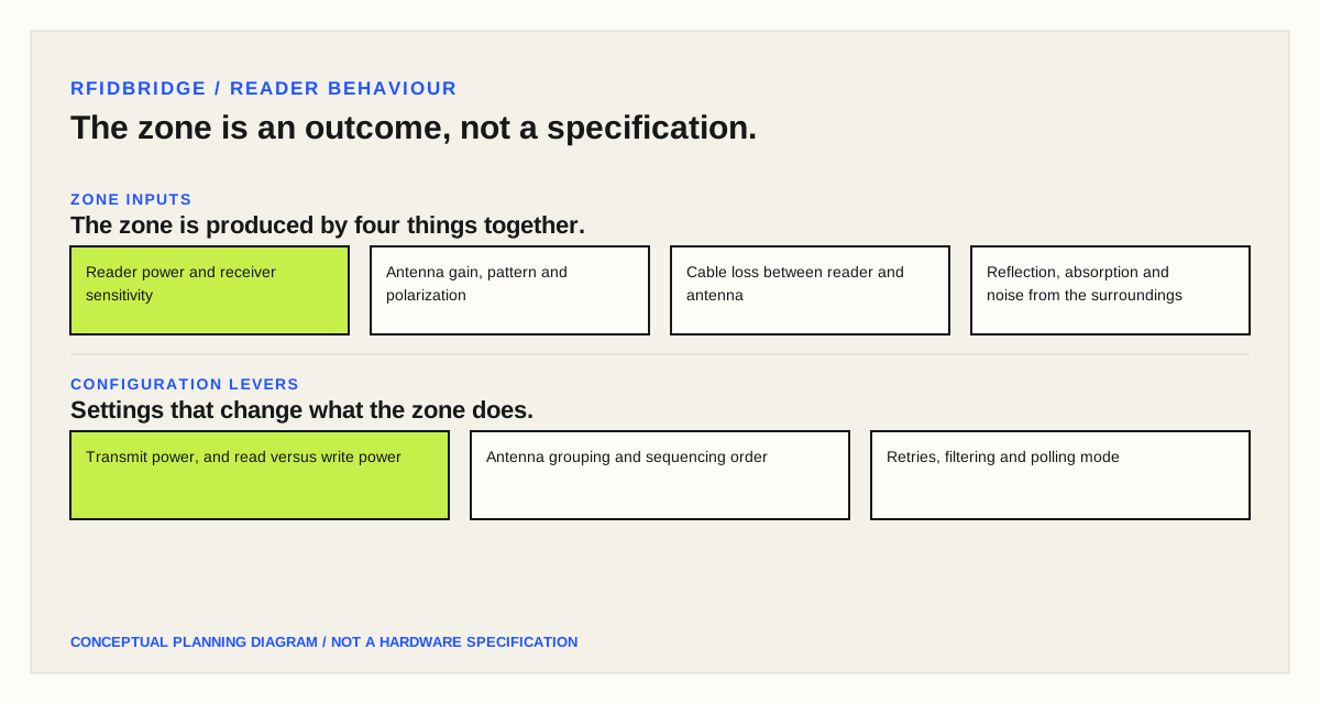
The interrogation zone is an outcome of reader power, antenna pattern, cable loss and the surrounding material — not a fixed distance printed on a datasheet.
01 / FIELD NOTE
Keep the decision tied to the operating context.
An interrogation zone is the volume in which a reader can reliably power a tag and receive its reply. It is made of the reader, its antennas, the cable between them, any attached peripherals and — decisively — the surroundings the equipment is installed in. Two installations running identical hardware can produce very different zones because the environment is part of the system.
Objects in and around the zone reflect, absorb and scatter radio energy. A reflection can arrive at a tag at a useful phase or a destructive one; absorbent material removes energy that would otherwise have reached the tag; and equipment sharing the band raises the noise floor the reader has to detect a reply against. The practical consequences are reads you did not intend, reads that should have happened but did not, and a system that processes fewer items per minute than the workflow assumed.
The reader itself performs three jobs. It powers passive and semi-passive tags by radiating a carrier, it manages the two-way exchange with each tag, and it converts between the analog radio signal and the digital data the rest of the system uses. Readers with enough processing power to filter and aggregate reads before forwarding them are usually described as smart; readers that pass raw observations upstream depend on middleware to do that work. Most current equipment is in the first group.
Physically, a reader contains an oscillator that generates the carrier, a transmitter that amplifies and modulates it, a receiver that amplifies and demodulates the very much weaker tag reply, and a control unit. That control unit runs the device, manages its network connection and its memory, and increasingly does its radio work in a digital signal processor, which is why radio behaviour can change with a firmware update rather than a hardware revision.
A monostatic reader transmits and receives through the same antenna, switching between the two roles internally. A bistatic reader dedicates separate antennas to transmit and receive, which typically means more antenna ports on the same unit. That choice matters at design time because it changes how many antennas a single reader can drive and where they can be placed.
Antenna behaviour is what most often decides whether a zone works. Gain shapes the pattern: higher gain produces a longer, narrower beam, lower gain a shorter, wider one, and the common 8.5 dBi class sits in the middle of that range. Polarization decides which tag orientations are favoured. A linear antenna concentrates its energy on one plane, so it reaches further and penetrates dense material better, but it reads poorly when a tag is rotated out of that plane. A circular antenna splits its energy across two planes, giving up range in exchange for reading tags whose orientation cannot be controlled. A mixed pallet usually argues for circular; a conveyor where every label faces the same way argues for linear.
In a fixed installation, overlapping antenna coverage is the standard way to remove the gaps that a single pattern leaves. The radiation plot supplied with an antenna describes the shape the manufacturer measured, which is a starting point for placement and not a prediction of your building.
Configuration decides how the installed power is spent. Transmit power is usually the first setting to review, because it sets both how far the zone reaches and how much a neighbouring zone is disturbed; it may be expressed in watts, milliwatts, decibels or as a percentage of the regional maximum, and some equipment allows read and write power to be set separately. Antennas can be grouped to act together and can be sequenced in a chosen order. Retry counts decide how long a reader keeps looking for new tags before it reports. Filtering lets a reader act only on part of the population it can hear, so a dock-door reader can be told to report pallet tags while ignoring case tags. Polling decides whether the reader scans continuously, at intervals, or on demand.
Those settings are what the common reading modes amount to. A conveyor mode reads in fast intervals with few retries, which suits a few tags that are briefly in view. An inventory-style mode reports on change — it watches a population over time and signals when a tag appears or disappears. The names differ between manufacturers; the underlying trade-off between speed and certainty does not.
Because the zone is an outcome rather than a specification, it is established by measurement on site. Set the power and antenna configuration you intend to ship, place the real items with their real tags in the real orientation, and read the zone the way the workflow will. Record where reads are reliable, where they are marginal and where they fail, then decide whether the fix is power, placement, antenna choice, or a change to the process.
02 / ZONE INPUTS
The zone is produced by four things together.
- Reader power and receiver sensitivity
- Antenna gain, pattern and polarization
- Cable loss between reader and antenna
- Reflection, absorption and noise from the surroundings
03 / CONFIGURATION LEVERS
Settings that change what the zone does.
- Transmit power, and read versus write power
- Antenna grouping and sequencing order
- Retries, filtering and polling mode
Bring the item, material, movement, target read and system context to a sample or project review.
Request a sample test